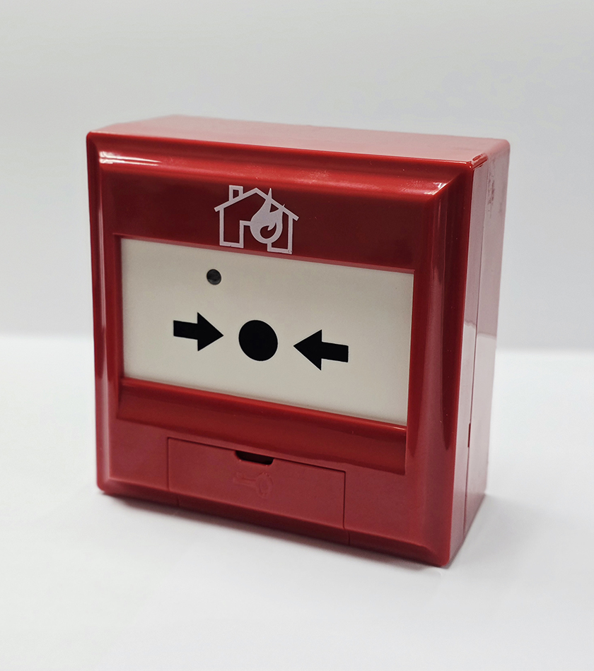
TX Series manual call point has a beautiful structure and wiring is easy and reliable. It alarms by the output current. It can be simply connected to compatible conventional fire alarm system from various manufacturers. It featured with “Plug and Play” installation.
When there is a fire, pressing the plastic resettable element on the manual call point can send fire signal to fire alarm control panel. After the control panel receives alarm signal, encoded information of manual call point and installation position will be displayed and an alarm sounds.
Operating Principle
This manual call point adopts depressing alarm type. It is self- locked by mechanical structure to reduce triggering possibility by mistake. Press plastic resettable element of manual call point, red indicator of fire alarm is on. Fire alarm information is sent to the controller. The controller displays fire alarm information.
Installation & wiring
Warning: Before installation, cut off power supply of the circuit and confirm all bottom cases are reliably installed.
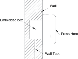
Installation: Incoming line conduit of manual call point adopts concealed installation (as shown in Fig. 1).
Fig. 1 Installation diagram of manual call point
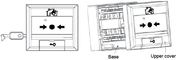
Removal method: Plug-in type is used between base and upper cover of this manual call point. A special key is inserted to remove the base and upper cover of the manual call point (as shown in Fig. 2).
Fig. 2 Removing diagram of manual call point
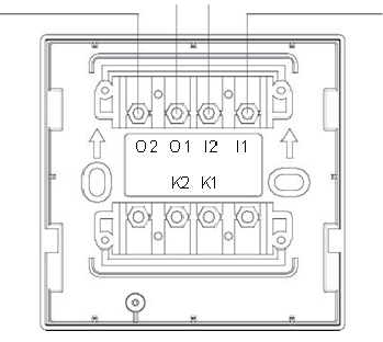
Terminals: as shown in Fig. 3
Fig. 3 Terminal description
I1 and I2: power supply input terminal, without polarity O1 and O2: cascade connection to the next equipment (no polarity) or connecting with 5.1KΩ terminal resistance. K1 and K2: normally-on signal output terminal (rated capacity 30V/0.1A).
Wiring requirements: In order to avoid wiring confusion, different colors shall be used for wiring; the connection between wire and manual call point base terminal shall be sealed (without exposed copper wire). Wiring method is as shown in Fig. 3. When wiring the base of manual call point, do not tighten incoming line and wire for cascading connection to the next base of manual call point onto one terminal.
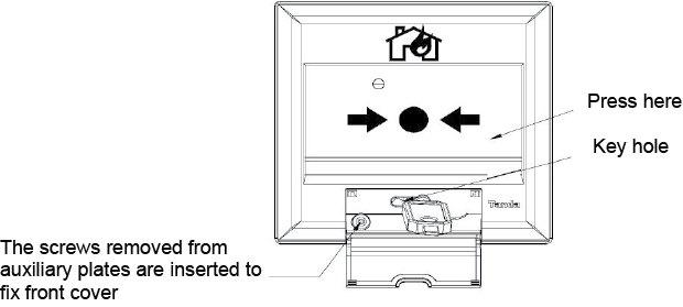
Plastic Resettable element of manual call point: After plastic resettable element of this manual call point is pressed, only a special reset key is used to reset it. If manual call point is to be reset after action, first open reset hole cover and then insert the key into key hole and rotate it by 90° clockwise. Reset diagram as shown in Fig. 4.
Fig. 4 Reset diagram of plastic resettable element
Testing
Warning: After all equipment is installed, power on
Before manual call point is tested, related management department shall be notified that the system will be maintained and the work will stop temporarily. At the same time logic control function of area or system to be maintained shall be cut off to avoid unnecessary alarm linkage.
Press plastic resettable element of manual call point. Red alarm indicator of manual call point shall be on.
After testing is over, reset key is used to reset manual call point and related management department is notified that the system restores normally.
During the course of test, check if wiring of unqualified manual call point is normal. Then test it again. If it does not pass the test, it shall be returned for repair.
Technical Parameters
Operating voltage: DC24V, 12-28V
Operating current:
Normal current: 0mA
Alarm current: ≤30mA
Output capacity: Rated DC30V/0.1A passive output contact signal and contact resistance ≤100mΩ
Type of starting parts: Reusable
Start type: Press plastic resettable element manually
Reset type: A special key is used to reset it. After an alarm is sent, open the key cover of the manual call point and insert the key to rotate by 90° to the right.
Status indicator: Fire alarm indicator (red). In normal state, the red indicator is off; after alarming, it is normally on.
Wiring system: Two-wire system, without polarity
Operating environment: Indoors, temperature -20°C ~ +55°C, relative humidity ≤95% RH, without condensation